|
|
|
Kategorie
|
|
Informacje
|
|
Polecamy
|
|
|
 |
|
|
Dla tego produktu nie napisano jeszcze recenzji!
 ;
Dokładna dokumentacja, pomogła w szybkiej naprawie telewizora. Dziękuję!
 ;
jedyne do czego mogę mieć zastrzeżenie to jakość zdjęć zawartych w przesłanej instrukcji serwisowej ponieważ są fatalnej jakości, praktycznie nieczytelne. tak poza tym jestem zadowolony to jest to czego szukałem.
;
Wszystko w porządku.
Instrukcja czytelna i kompletna.
Dziękuję.
all right!
thank you.
;
Bardzo dobra instrukcja. Zawiera wszystko co potrzeba, polecam!
;
Instrukcja jest OK. Schematy czytelne, opisane niektóre procedury.
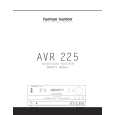
AVR225
harman/kardon
AVR125/225 DISASSEMBLY PROCEDURE
<1> TOP-CABINET(21) REMOVAL 1. Remove 13 screws(S1,S7) and then remove the Top-cabinet. <2> FRONT PANEL ASS�Y REMOVAL 1. Remove the Top-cabinet, referring to the previous step<1>. 2. Disconnect the connect (BN72-Card canle)) on the FP PCB(37-1) from connector(CN72) on the Input PCB(39-1) 3. Disconnect the lead wire(BN80-8P) on the FP PCB(37-1) from connector(CN80) on the Main PCB(38). 4.Disconnect the lead wire(BN16-8P,BN10-4P) on the Tone PCB(37-3) from connector(CN16,CN10) on the Connect PCB(37-7). 5. Disconnect the lead wire(BN41-6P) on the Tone PCB(37-3) from connector(CN41) on the Video PCB(39-2). 6. Disconnect the lead wire(BN18-5P) on the Digital input PCB(37-8) from connector(CN18) on the Input PCB(39-1). 7. Disconnect the lead wire(BN81-6P,BN83-2P) on the FP PCB(37-1) from connector(CN81.CN83) on the Trans PCB(39-3). 8. Disconnect the lead wire(BN88-2P) on the Main PCB(38) from connector(CN88) on the Moms PCB(37-5). 9. Remove 1 screw(S10) and then lead wire(JW82-2P) on the Phone PCB(37-4). 10. Remove 9 screws(S1) and then remove the Front Panel ASS�Y. <3> TONE PCB(37-3) REMOVAL 1. Remove the Top-cabinet, referring to the previous step<1>. 2. Remove the Front Panel ASS�Y, referring to the previous step<2>. 3. Pull out the Volume Knob ASS�Y & 3 Rotary Knobs(5). 4. Remove 1 Nut(40), 1 Washer(41) 5. Remove 7 screws(S2) and then remove the Tone PCB(37-3). 6. Disconnect the lead wire(BN84-5P,BN90-2P) One the Tone PCB(37-3) from connector(CN84,CN90) on the FP PCB(37-1) 7. Disconnect the lead wire (BN87-6P) One the Tone PCB(37-3) from connector(CN87) on the Phone PCB(37-4) <4>PHONE PCB(37-4) REMOVAL 1. Remove the Top-cabinet, referring to the previous step<1>. 2. Remove the Front Panel ASS�Y, referring to the previous step<2>. 3. Disconnect the lead wire (BN87-6P) One the Tone PCB(37-3) from connector(CN87) on the Phone PCB(37-4) 4. Remove 2 screws(S2,S3) and then remove the Phone PCB(37-4) . <5>POWER LED PCB(37-6) REMOVAL 1. Remove the Top-cabinet, referring to the previous step<1>. 2. Remove the Front Panel ASS�Y, referring to the previous step<2>. 3. Remove 2 screws(S2) and then remove the Power led PCB(37-6). 4. Disconnect the lead wire(BN88-4P) from connector(CN88) on the FP PCB(37-1). <6>FRONT PCB(37-1) REMOVAL 1. Remove the Top-cabinet, referring to the previous step<1>. 2. Remove the Front Panel ASS�Y, referring to the previous step<2>. 3. Remove the Tone PCB(37-3), referring to the previous step<3>. 4. Remove the Phone PCB(37-4), referring to the previous step<4>. 5. Remove the Power led PCB(37-6), referring to the previous step<5>. 6. Remove 6 screws(S2) and then remove the Front PCB(37-1)
18
|
|
|
> |
|